Hi! My name is Brian and this blog is intended to be an instructional build log for the more advanced multirotor designer. This blog will detail the components I used as well as reasons why I chose each component.
My goal was to build a quadrotor that would offer optimal dynamics for combo fpv and aerial photography.
My basic constraints
• system must be large enough to carry a Gopro
• system must include a camera stabilizing gimbal
• system must not have the props or arms in the aerial shot (props out of the shot (POS))
• system should be optimized for best possible flight time
• system should be durable and able to withstand a modest crash
After researching multiple quad frame designs I decided to base my frame off of the H design. I chose to slant the arms forward (symmetrically of course) such that the angle between the front and rear two arms respectively would be 135 degrees to provide valuable real-estate in the center or body of the craft for mounting the flight controller and battery. Below is a basic list of the components I used in my build and a general reason for that selection.
Airframe Body: (Carbon Fiber plate)
I chose to construct my air frame body out of carbon fiber plate primarily for its strength and light weight properties. It should be noted that while the resin of most carbon fiber composites is non conductive the carbon matrix itself is and can easily cause a short to ground. Given carbon fibers abrasive nature you should always take care to protect all wiring from chafing.
Rotor Arms: (Basic DJI injection molded arms)
I chose to utilize the DJI arms in my design primarily for their availability and low cost. I also chose these arms to be key failure points in a crash as it will be very easy to replace an arm rather than my airframe (this characteristic has not been test yet).
Flight Controller: (DJI NAZA V2)
After testing both the KK2 and NAZA I decided to use the NAZA primarily for its solid platform and support as well as its seamlessly integrated GPS. I also like the configuration options available with the assistant software. One thing that I preferred with the KK2 was the direct PID gain control vs the DJI gain control (still trying to figure these out).
Motors: (Sunnysky 2216-12)
These motors were chosen from an iterative process. I chose these motors after designing the basic frame and summing up the approximate weights of all components + frame.
ESC: (Hobby King Q-Brain 25A)
I chose to use the Q-Brain to help clean up and minimize the wiring. Several reviews suggested that the Q-Brain was susceptible to over heating so I have been monitoring my ESC temperature with a thermal imaging camera. So far I have not seen any critical temps. I suspect most of the bad publicity stems from either pore ESC sizing or bad manufacturing, just in case; my Q-Brain is directly mounted to an aluminum plate to act as a heat spreader (it works well). So far I am happy with this ESC configuration.
GoPro Gimbal: (Tarot 2D)
I selected the Tarot 2D gimbal for its small size and numerous customize-able features. I also like its mounting system.
Tx: (Frsky Taranis)
Awesome controller!!!!!
Rx: (Frsky X8R)
SBUS......!!!!!!!!
And now the build pics!!!!
I decided that the most effective way to design the quadrotor that I wanted was to first construct my design in a 3D virtual CAD program. CAD programs often have a very steep learning curve so this may not be the best route for everyone. I found the most important steps, to be the initial part selections and geometric layout. It is important to understand that the design process is an iterative one, therefore you should expect to backtrack several times during the design process to make part selection changes as well as dimensional and part position changes. That's just the way it is!! The more models you build the better you will get at determining these initial constraints but their will almost always be some form of iteration (just ask Boeing and Bell).
 |
| 3D rendering of my quad design (helps to visualize the final design) |
 |
| Exploded view of my design (no wires & cables in model yet) |
Once the virtual design was perfected it was time to buy the parts and materials. I decided to construct the body of my quad out of carbon fiber plate. Carbon fiber was chosen because of its strength rigidity and light weight. I hand cut and drilled the carbon fiber plates (a note to anyone who may want to try this, carbon fiber is nasty stuff wear a mask and goggles or that night will be an itchy one).
For the arms of my quad I chose to use the pre-designed DJI arms because they were readily available and cheap. My arms are designed to fracture before they tear through the carbon fiber plate, but this has not yet been tested???
 |
| Looking good! |
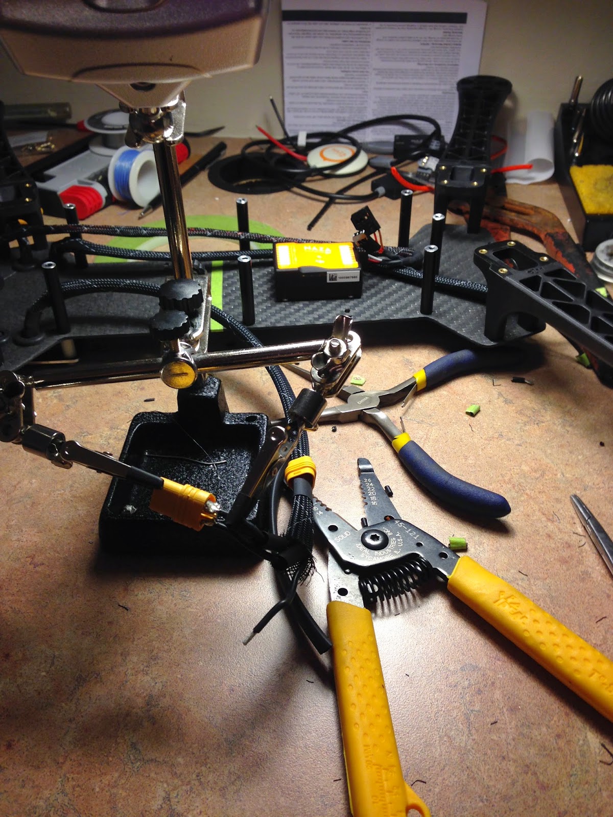
Time to run the wires! This part will test your patience if you are a perfectionist like me. Best advice I can give you is take your time and experiment before you cut wires always lay out the route first before you cut. The soldering iron is your friend and can make quick repairs, also if you will be using a soldering iron get some tip tinner and flux (makes your life so much easier). Also electrical tape SUCKS!!! use heat shrink!!
A word on ruggedization (DO IT). Wire insulation can and will chafe and carbon fiber is conductive & abrasive, so i find it best to protect your wires. I like wire braid as it is flexible but you can also use spiral wire wrap its up to you but use something. I have seen some wiring jobs on otherwise well designed multirotors and let just say if Boeing or Airbus routed wires that way then you wouldn't see me on any planes.
 |
| I epoxied the solder joints of all the 3 phase leads to provide strain relief. I also left some extra slack in the main harnesses so if their is an ESC failure I can simply cut the wires and solder them to a new Q-Brain. |
 |
| I used rubber grommets to go through the frame. This made for a very neat setup. |
 |
| I soldered new longer BEC leads to reach the flight controller |
 |
| Having the ability to make your own connector is nice. Crimping these little guys isn't easy but with a little coaching it can be done effectively (thanks Sam) |
 |
| These three contact keyed connectors will allow the arms to be removed if necessary and will make reattachment a snap with the right labels |
 |
| Nice clean wiring harness |
 |
| In this pic you can see the rugged custom back shells on the yellow connectors in the background |
|
 |
| Braiding the one receiver wire! SBUS got to love it |
 |
| Camera gimbal rails |
 |
| Screws to mount the gimbal rails |
 |
| Ta da!! Now hopefully this double vibration isolation doesn't induce any noticeable resonant frequencies? |
 |
| Looking good!! |
A word on balance: In a quadcopter balance is everything!!! You must equally load your motors otherwise the flight controller will need to compensate by increasing the speed and hence thrust to balance the axis couple.
Their are three axes to the quadcopter (and any aircraft at that matter). These axes are as follows
- X axis (Roll axis): +X points forward!
- Rotation about this axis is your Roll. It is important to note that the Roll (or rotation about the X axis is controlled by balancing (or unbalancing) the resultant right and left motor thrust couples about this axis.
- Y axis (Pitch axis): +Y points to the right!
- Rotation about this axis is your Pitch. It is important to note that the Pitch (or rotation about the Y axis is controlled by balancing (or unbalancing) the resultant forward and aft motor thrust couples about this axis.
- Z axis (Yaw axis): +Z points down!
- Rotation about this axis is your Yaw. It is important to note that the Yaw (or rotation about the Z axis is controlled by balancing (or unbalancing) the resultant motor gyroscopic couples.
Note: To balance your quad the center of thrust (COT) must coincide with the center of gravity (COG) of the aircraft. Now because after the design process the COT is often fixed it is best to locate this point in the XY plane on the air frame and drill a small hole, that way we can hang the craft at the designed COT and then manipulate the COG to coincide at this point. The 2D COT is where the Roll and pitch axes meet!
I have seen many people use the string method attached to diagonal motors to find the center of thrust and this method will work as long as their is symmetry about both axes. If symmetry does not exist then you must find the center of thrust by balancing the moment arms about the non symmetric axis.
A perfect example of a non symmetric air frame that is balanced is the TBS Discovery. Notice in their manual that the COG does not coincide with the coincident diagonal motor line (what they call the the center of thrust). Now it would be foolish to create an un-balanced craft (and i can assure you they did not do so). The true center of thrust lies at the labeled COG which is in fact the Pitch axis.
Now before i go on i should say that all of these calculations are under the static assumption F=ma=0, and a dynamic analysis (F=ma=mdv/dt) is far beyond this log.
 |
| TBS Discovery Mechanics |
 |
| Balanced so nicely. |
OSD time....My rig was designed for FPV and video so naturally I wanted a way to print valuable data onto my new FatShark Attitude goggles! I chose the iOSD module from DJI because it was small and very easy to integrate with the fatshark camera. All the iOSD is really doing is stamping the data as an overlay onto the camera image (in real time). To iterate the iOSD into the fatshark module I had to splice in series a connector using a mock PCB board. This connector then plugs into the iOSD and ta da OSD!!!
 |
| PCB board for splicing in the iOSD |
 |
| The complete FPV system |
 |
| PCB board all soldered up |
 |
| Almost finished!!! |
Transport Case Build
Once you build your multirotor your obviously going to want to use it. You will quickly realize that transporting these things can be quite a hassle. You end up forgetting an important part or something gets broken. If you plan on using your multirotor more than just occasionally then you will want to design or purchase a rugged transport case for the multirotor and its subsystems (this is a must if you plan on traveling long distances or shipping your machine).
I work for a small LiDAR manufacturing company and we ship large very expensive and very delicate systems all over the world, and i can say from first hand experience that any shipping company will just about try to destroy the package that they are shipping for you. The more caution and warning signs you place on the package the harder they try to destroy it (I'm kidding of course ;-) but it almost seams like this is the case). But anyway if you are going to ship of travel with your drone then i would seriously suggest that you invest in a transport case such as a Pelican Case, SKB, or Hardigg Storm Case. These cases are designed to take a beating so your contents don't. Many people and forums would suggest that Pelican Cases are the best but for the most part they are all pretty comparable you just need to find one that fits your multirotor.
For my drone i decided that i wanted to be able to pack it away without removing the arms or props. I also wanted to include all other components that would be required to complete a mission (i feel like NASA).
Case Specs
- Case Brand: SKB
- Model: 3I-2918-10
- Inside Dimensions: 29 x 18 x 10.75 inches
- Foam: Pick and pluck ester foam
- Military Specs
- MIL-C-4150J
- MIL-STD-648C
- MIL-STD-810F
Case Contents
- Quadcopter
- Transmitter
- FPV goggles
- Storage for 2 LiPO batteries (don't store them in here!!)
- Mini tool case for field repairs
- Small 1150 Pelican case for storage of GoPro, LiPO charger and some other small components
When setting up your case the most important thing to do is layout your setup. Pick and pluck foam is great for straight and vertical cutouts but angled lines are not possible to do. Because my quad had 4 slanted arms i wanted to create a custom cut out of my quad. In order to do this i needed to cut foam. The best way to cleanly cut ester foam is the hot wire method. For my setup i used my DC power supply to run a current through some guitar wire. After some testing i determined the proper current and voltage to get the wire to the right temperature to cleanly cut the foam (take care when cutting pick and pluck foam as the wire has a tendency when forced to follow the perforated sections rather than your template). To layout my quad i printed a full size plan view of my quad and cut it out to use as a template. I then pined the template to the foam and used it as a guide to cut the profile. Once i cut out each of the layers of foam i was ready to glue them to each other and to the case (i used 3M spray auto headliner and fabric adhesive). After everything was glued up i decided to spray the top layer (and all the cavities) of the foam with Plasti dip. This strengthened the foam especially at the adjacent cube perforations and i read that it will also increase the life of the foam.
All in all it doesn't really matter whether or not you design a good looking case or if you just throw blocks of foam in to the case around the quad. All that really matters is that your quad is protected (although it is nice to be organized).
and now for some pics....
 |
| Remember to layout your setup |
 |
| My temporary foam cutting setup. |
 |
| As you can see you need to keep constant tension on the wire (like my FatShark guide fence). |
 |
| The bottom of the wire i soldered to a pin connector. |
 |
| My template pined onto the foam. |
 |
| The first cut out!! |
 |
| Not perfect but pretty good! |
 |
| With top foam in-place. |
 |
| I decided to not use the top foam as i felt it was unnecessary and would make the quad more difficult to remove (i will keep it for repairs). |
 |
| All done!! Remember to keep your case open for the next few days to let the glue and Plasti Dip fully outgas. |
 |
| Everything in-place!!! Looking Good! |
Ok now thats all their is to it! Looks like its time to go and get some great video footage but at least now all i have to do is transport one case.
Let me know what you guys think about my quad and transport case.
Thanks
Brian


It's very very nice looking drone.
ReplyDelete